The type and direction of the deck (for beam supported floors) or slab (for concrete slab floors) determines which members support an area and thus the loads that are attributed to the members. Unless the deck/slab is defined as “Two Way”, the distribution direction is indicated by the Deck Angle (for beam supported floors) or the Direction of the slab definition (for concrete slab floors).
You may place area loads, line loads and point loads directly on a one way deck or slab and it will be automatically attributed to the supporting beams, columns and walls. For one-way distribution, loads are attributed to supporting members based on simple beam theory. The deck or slab is viewed as a simple beam that spans between supporting members. Therefore, the support closest to the applied load receives a higher percentage of the load based on the span length and load location.
In this way, Area Loads and Tapered Area Loads are attributed to beams and columns as distributed loads. Although at times it is beneficial to draw area loads beyond the diaphragm edges, only loading within the edges is attributed to the model. Area loads that are defined outside the diaphragm edges will not be applied to the solved model.
Note
If two area loads are drawn over the same location then the load that was drawn in last (i.e. the top-most load) will govern for that region. In this way, the area load polygons can be seen as a "stack" of loads where the one on top of the stack has the highest priority or ranking and will supersede any of the area loads that are lower down in the stack.
The one exception to the stack analogy are the"Additive" area loads. Any loads that are defined as additive will be added together first. The,n the total will be added to the normal (non-additive) area load that is highest in the stack to determine the total area loading in that region.
For additional advice on this topic, please see the RISA Tips & Tricks webpage at risa.com/post/support. Type in Search keywords: Additive Area Loads.
Note:
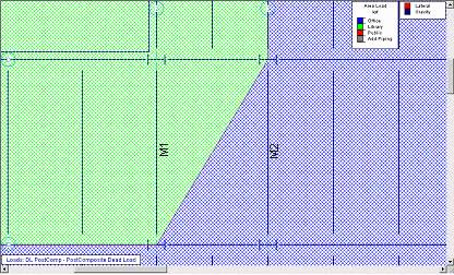
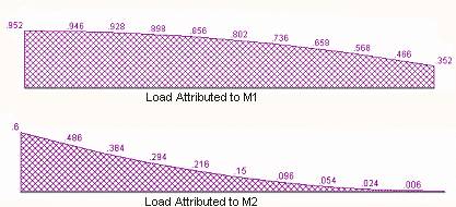
For both area loads and line loads there are cases where the resulting distributed loads are actually parabolic or cubic in nature. The partial deck loading shown in the following image is a good example of a loading condition that produces parabolic loads. RISAFloor approximates the parabolic load as a series of trapezoidal distributed loads as shown in the following diagram.
For two way decks, Area Loads are each divided into meshes of smaller areas which are assigned an equivalent point load. Each point load is attributed to the surrounding members based on their relative distance to the point load. The size of the mesh may be set on the Global parameters with smaller mesh sizes giving more accuracy. Beams that receive area loads are divided into ten segments and the area loads that fall on these segments are “smoothed” into equivalent distributed loads. Although at times it is beneficial to draw area loads beyond the diaphragm edges, only loading within the edges is attributed to the model. Area loads that are defined outside the diaphragm edges will not be applied to the solved model.
Similarly, Line Loads on two way decks are divided into smaller loads based on this area load mesh size. These loads are then attributed to their supporting member and converted into equivalent distributed loads. If a line load is applied outside of a diaphragm edge, only the portion of the line load that is directly supported by a beam or wall will be attributed.
On two way decks, Point Loads are attributed to the surrounding members based on their relative distances to the point load. Point loads that are applied outside of a diaphragm edge, will only be attributed if they are directly supported by a beam, column or wall.
Because of the nature of the FEA solution, the two way load distribution for concrete slab floors will not always exactly match your hand calculations. This is because the program analysis is based on a load distribution due to element stiffness not tributary area.
The load is attributed to supporting elements based on relative stiffness which is increased by the slab (plate) floor. Because of this, supporting columns at the interior of the slab will be stiffer (and therefore attract more load) than those along the edges.